

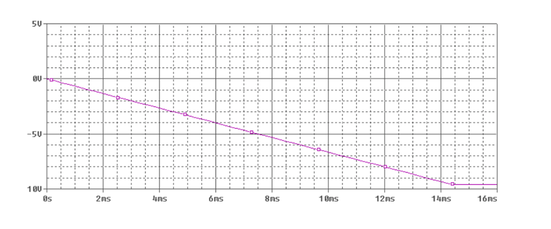
The goal is to model an operational amplifiers in PSpice and graph the voltage as a function of time.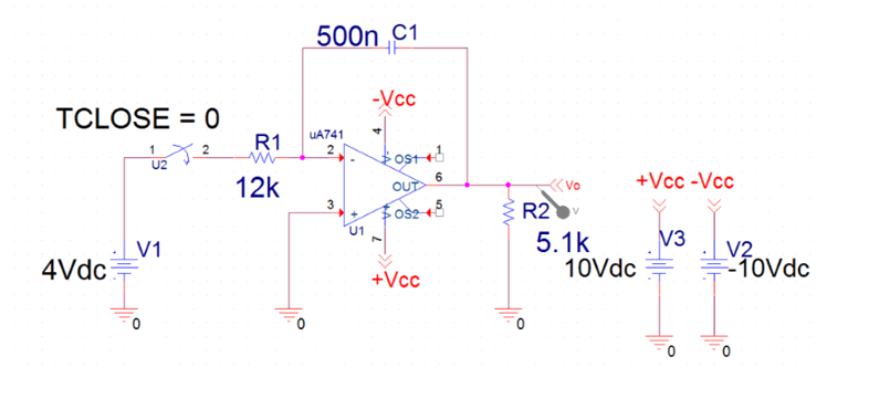
DC Op Amps
Op Amps can add, subtract, multiply or divide input voltage signals. This project analyzes the negative voltage rise of a resistor, capacitor, and op amp circuit. Below is a schematic constructed in PSpice.Ideal Op Amp Characteristics
At saturation, the magnitude of voltage output equals the magnitude of the power voltage of the Op Amp (\left|V_o\right|=\left|V_{cc}\right| ). Ideally the input internal resistance of the op amp is infinite and the output internal resistance is 0. Therefore, the “positive” voltage input is equal to the “negative” voltage input. These are called ideal characteristics. V_p=V_n R_{in}\rightarrow \infty R_{out}\rightarrow 0 -V_{cc}=\le V_o\le V_{cc} General procedure to solve for the output voltage- Solve for V_p or V_n (whichever is not connected to V_o ).
- Use Node-Voltage Method for the one connected to V_o .
- Substitute Equation from step (1) and (2) and solve.